Variation of the resistance
Content of this page :
1. Introduction of the experiment.
2. Aim of the experiment.
3. Tools of the experiment.
4. Steps and methods of the experiment.
5. Parameter, Theory and Final law of the experiment.
6. Medical application and advantages of the experiment.
1. Introduction of the experiment:
The temperature coefficient of resistance is the parameter that shows the relationship between the variation of resistance with an increase in temperature. The Resistance of the metal increase linearly with an increase in the temperature.
2. Aim of the experiment:
-Measurement the Variation of the Resistance of a wire with Temperature.
-Measurement of The Temperature Coefficient of Resistance.

3-Tools of The experiment
· Metre (Wheatstone) bridge.
· Dry cell.
· Resistance box.
· Sensitive galvanometer and protective resistance.
· Thermometer 0-100 °C in 0.5 °C.
· Beaker.
· Ice.
· Test-tube containing a coil of wire immersed in paraffin.
· About 2 metres of iron wire s.w.g. 34 d.c.c. is suitable for the coil.
4. Steps and methods of the experiment:
Immerse the test-tube in a beaker containing finely crushed ice and water and leave for some time. Meanwhile connect up the usual metre bridge circuit as shown in the diagram. When the thermometer indicates 0°C or thereabouts find the resistance of the coil by means of the metre bridge, adjusting the resistance of the resistance box to obtain a balance point approximately in the middle of the bridge wire. Record the temperature.
Replace the ice-water mixture by tap-water and again determine the resistance of the coil, reading the temperature as soon as the point of balance has been found. By means of a low bunsen flame slowly heat up the bath and measure the resistance of the coil at approximately 10 °C intervals of temperature, recording the exact temperature of each observation.
5-Parameters, Final Law of The experiment
Parameters:
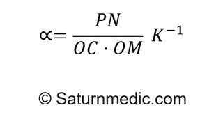
PN: Is the increase in resistance of a resistance.
OC: The Resistance measured in ohm (Ω).
OM: The Rise in Temperature.
K: Unit Measurement of The Temperature.
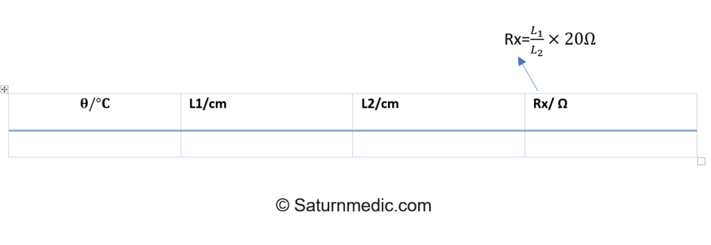
𝛉: Temperature (°𝐂).
L1: First Length (cm).
L2: Remaining Length (cm).
Rx: Final Resistance (Ω).

Final Law:

6-Table of The readings:

7-Medical application
For a diode laser to maintain its frequency, output power, current and temperature, careful regulation of parameters is required. To best manage costs, the Physics Department at California State University looked to construct its own low-cost, low-noise current source for use with its in-laboratory diode lasers. To generate a suitably stable laser stream, the current sense resistor needed to be resistant to both internal and external temperature drifts, have a high-power rating, and a low thermal EMF. The most critical element of the current driver is the sub-circuit, responsible for current regulation since laser stability must not exceed overall sense resistor stability. In this application, the use of traditional commercial current controllers was too cost-prohibitive. The viable resistor solution therefore needed to be both low-cost and high-precision.
